In a nutshell, I want to hook up this 2-channel Ford AM/FM radio which uses a common ground to my 4-channel booster.
OK, here are a couple pictures of what I've got, along with a factory '79 wiring schematic for the AM/FM stereo radio (click thumbnails to enlarge):
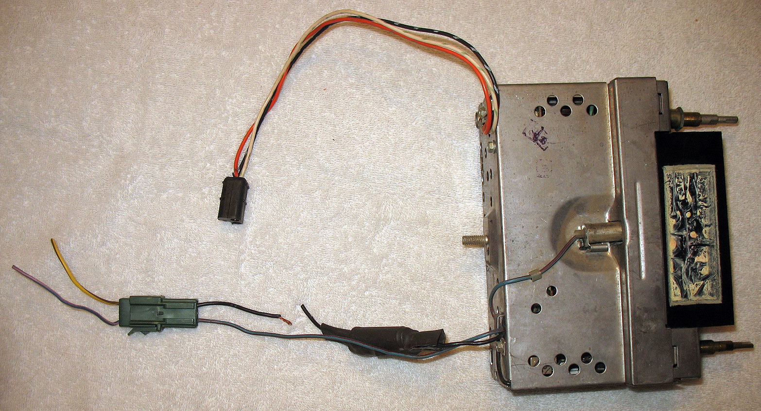
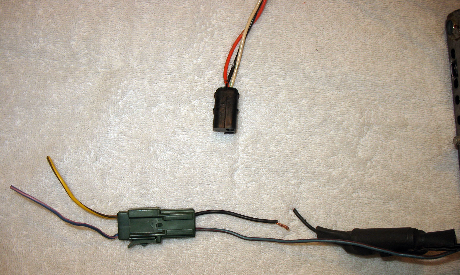

As you can see, there are two clusters of wires coming off this radio. There's a three-wire plug which I'm assuming is for the speakers, and the two-wire plug. Let's tackle the two-wire plug first.
There's a yellow wire w/black tracer coming into the green connector. I'm assuming that this is the 12V power source, correct? This wire turns into a black wire which then goes into a bundle of something. What is that bundle? I didn't want to unwrap it if unnecessary. So does this radio use a chassis ground instead of a standard black ground wire? The blue/red wire is for the dial illumination light.
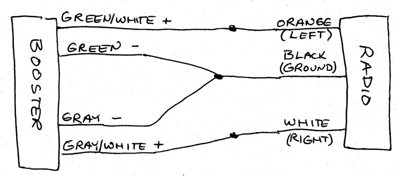
OK, now the speaker connections. I've got my truck set up with four speakers, two in front and two in back, each with a positive and negative connection. However, this radio is only set up for two speakers (white/green and orange/green) with a common ground. I want to hook this up to my booster/equalizer. I'm including the wiring schematic for the booster:
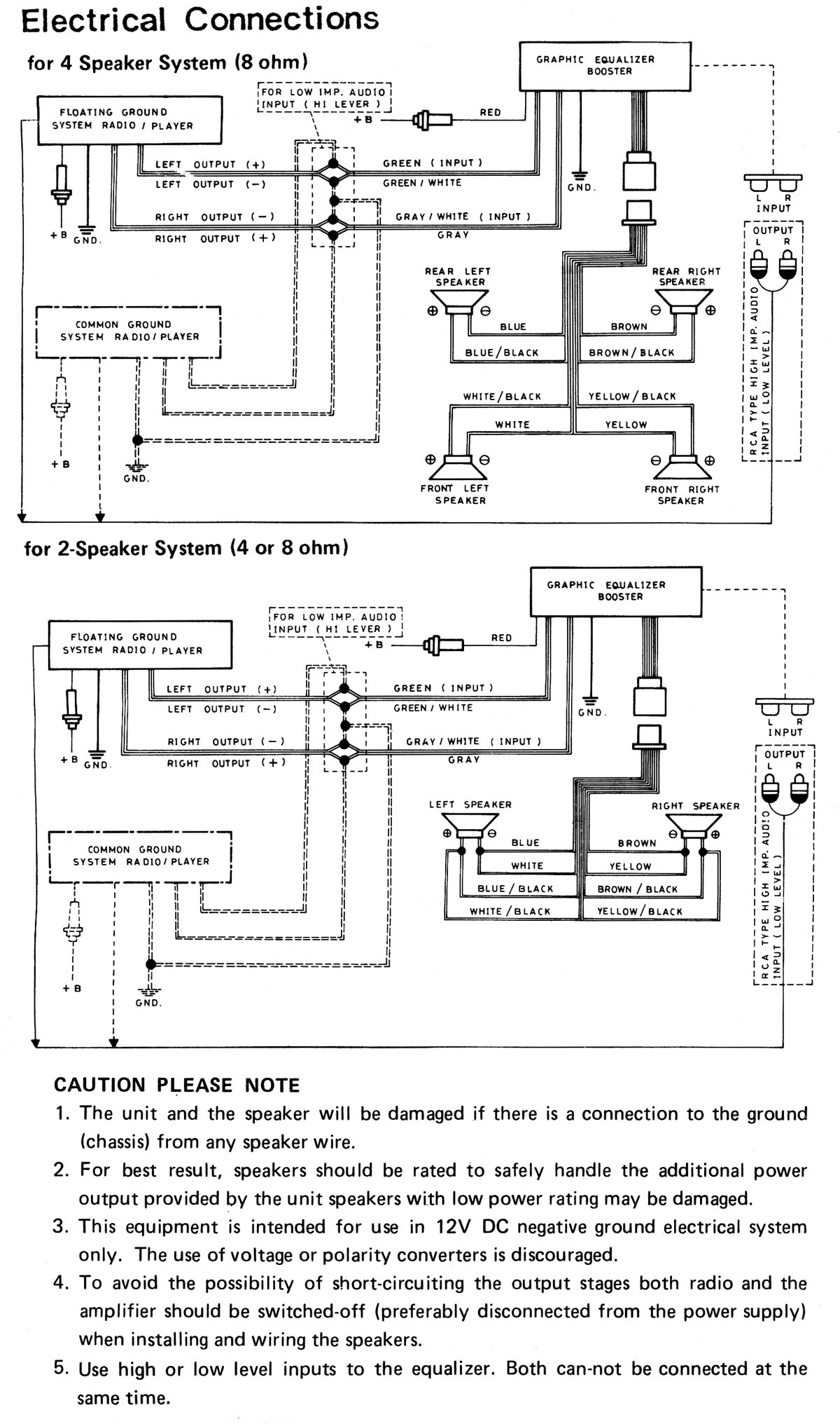
What's confusing me (and trust me, it ain't hard to do!) is that it appears in the above booster schematic that the speakers are grounded to the chassis, yet the warnings specifically state NOT to do that. As shown in this schematic, the booster has green & green/white input for the left channel, and gray & gray/white input for the right channel...but I'm not sure which is the left and right channels on the Ford radio.
So...how do I hook up this Ford AM/FM with a common ground to this booster without damaging anything?