I am doing a total rewire with a kit from Painless and need some help.
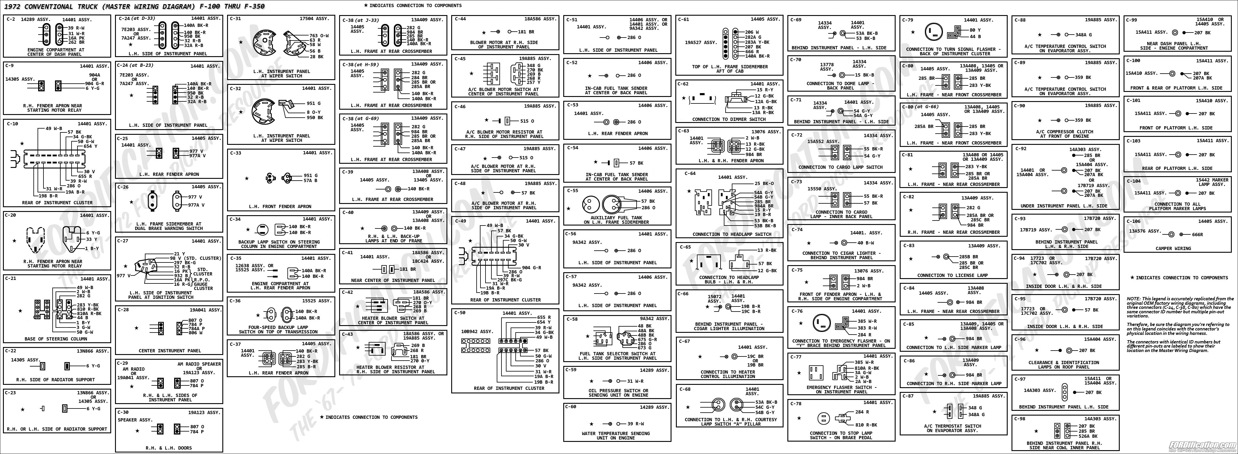
I'm looking at the schematic found here in the site for a '72 F100 custom. It shows the factory printed circuit connector wires for the instrument panel, but it does not match up to mine. The schematic shows 12 possible connection points with 9 wires. My truck has the same 12 point connector but has 11 wires, and the location of the color coded wires are not matching the schematic.
I realize the 2 extra could have been added at some point, but I was wondering if I am looking at the right schematic in the first place. Is there another resource for instrument panel wiring?
Do you have the full gauge package in your truck? ie: amp, oil, fuel, temp.
Or warning lamps for oil and amp?
That may be the difference. I know the amp gauge and the amp warning light use different wiring in the harness. Maybe it is different also at the plug to the cluster? Just a guess?
Let us know what you find.
Two-bit
Living life full throttle on the North Coast of America!!!
COOL - Thanks!!! It does match to C-49. I have the oil and alt lights, not gauges. Where does that fall into the bigger schematic? I thought at C-49 but I couldn't find the connector like the '72 quick reference diagram has. I need to see where all the wires go to.
Trace the foil to see where the connections are going and deduce what needs hooked up from there. I'd much rather restore a factory harness vs. deal with an aftermarket one.
Ranchero50 wrote:Trace the foil to see where the connections are going and deduce what needs hooked up from there. I'd much rather restore a factory harness vs. deal with an aftermarket one.
I know what you are saying, but there were too many splices and hanging wires. The ignition worked but not much else. Also, I decided to go aftermarket because of the extra circuits available, elec choke, elec fan, power antenna, cargo light, accessory, etc....
The issue i'm having is just making sure I am connecting correctly. I am doing the tracing but wanted a reference to confirm everything. I don't want to add power and blow some fuses!
Randy
1970 F100 Sport Custom Limited LWB, 302cid, 3 on the tree. NO A/C, NO P/S, NO P/B. Currently in 1000 pcs while rebuilding. Project thread: http://www.fordification.com/forum/view ... 22&t=59995 Plan: 351w, C4, LSD, pwr front disc, p/s, a/c, bucket seats, new interior and paint.
1987 F-150 XLT Lariat, 5.0/C6 auto.
OK, I'm hoping the answer to this question is as simple as I think. Basically, the only wires that are repeated in multiple circuits would be the red and black. Meaning, for example, the red-blue goes from ignition to starter relay. that color combo should not be used anywhere else on the truck. Therefore, because the C-49 schematic is not shown in the master, I can follow the color coded wires that are in the connector to know where they are supposed to go (and come from).
Yes and no. Ford has been very good about keeping the wire number and color consistent throughout the years. When I did my wiring integration for the diesel swap I wrote down the from - to of each wire, it's color, number and purpose and it worked out well.


