Davin,
I humbly apologize I thought you had it all worked out...

After re-reading I see you still had questions, my head is not as clear as it should be and the 2 noncontributory posters side tracked my train of thought. (we're trying to curb that behavior in the technical forums) I deleted there posts from the thread and unlock it. Your post has every right to be asked and answered here as others run into the same thing or may want to change theirs to the same setup. You were getting very good advice on it.
To add more info;
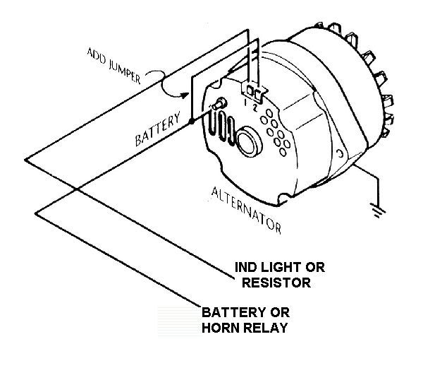
What you had with both the #1 and #2 wires connected together into the exciter wire was the problem, when the alternator starts charging it puts voltage on the #2 post which in turn was back-feeding voltage to the ignition switch through the exciter wire. The exciter wire is on the same supply circuit as the ignition wire to the coil so it made a voltage loop causing you to not be able to turn the engine off.
You were correct in your diagram of separating the 2 wires on the exciter wire and hooking the #2 post wire to the battery wire. It would be best to hook it up on the starter solenoid with the battery cable there, as it will get a more accurate sense to the regulator and the alternator will charge the battery better.
Here is a diagram that shows the same thing;
And as to the small yellow wire with the fuse, this was part (one of two wires) of the wiring for the Alt gauge, it can be wired back into the circuit but it is easier to just get a voltage gauge and it works much better.

Again I apologize for cutting the thread short.
Shayne


