When I connect a 7 pin trailer connector to our truck (which has a brake controller) and use the emergency flashers the brake controller transmits full brake to the trailer when the signal flashes, power goes away when the signals are not flashing or out. This results in a pulsating full brake application to the trailer. Glad I found this out while barely moving!!
I was told the turn signal device in the column could be the culprit. It is old but the signals work just fine with and without the trailer.
Should I order a new signal mechanism or keep searching for another short?? Locally, I can only get the cam repair kit up here.
The second problem is when the running or headlights are on with the trailer connected for 7 or 8 minutes I begin to trip an auto resetting relay and loose all lights to the truck and trailer. I may have fixed this last one with a wire I found chaffing on the steering column mount.
Thanks
Dan
7 Pin Trailer Wiring Issue
Moderators: FORDification, Thunderfoot
-
DGrant09

- New Member

- Posts: 177
- Joined: Wed Jul 11, 2007 10:20 pm
- Location: Palmer, AK
7 Pin Trailer Wiring Issue
09", F350, Cabelas, 6.4L
72", F250, CS, 390, 2 WD
72", F250, CS, 390, 2 WD
-
wildcard

- Blue Oval Guru

- Posts: 1045
- Joined: Sun Dec 04, 2005 5:40 pm
- Location: Texas
re: 7 Pin Trailer Wiring Issue
Sounds as if you have your elec. brake wire tied into your brake/signal wire somewhere, somehow.
As for the second one, sounds to me like a short in the trailer wiring or the plug. Be sure there are no stray strands touching inside the plug itself also. That could be the best place to start troubleshooting both problems. I've had it happen to me.
I'm no expert by a long shot, but if you only have problems with the trailer attached, it seems like all your problems are from the connector, back. Not in the cab. But then again that's just my Good Luck
As for the second one, sounds to me like a short in the trailer wiring or the plug. Be sure there are no stray strands touching inside the plug itself also. That could be the best place to start troubleshooting both problems. I've had it happen to me.
I'm no expert by a long shot, but if you only have problems with the trailer attached, it seems like all your problems are from the connector, back. Not in the cab. But then again that's just my
-
Thunderfoot

- 100% FORDified!

- Posts: 2207
- Joined: Tue Apr 17, 2007 2:34 pm
- Location: Idaho, Boise
re: 7 Pin Trailer Wiring Issue
Dan,
Mike58sacco is correct, this is somewhat normal...
The electronic Trailer Brake Controllers (TBC) have a wire that is hooked to the brake lights. This tells the TBC to activate the trailer brakes and then there is an inertia sensor in the TBC that tells how hard to apply the brakes (along with adjustments).
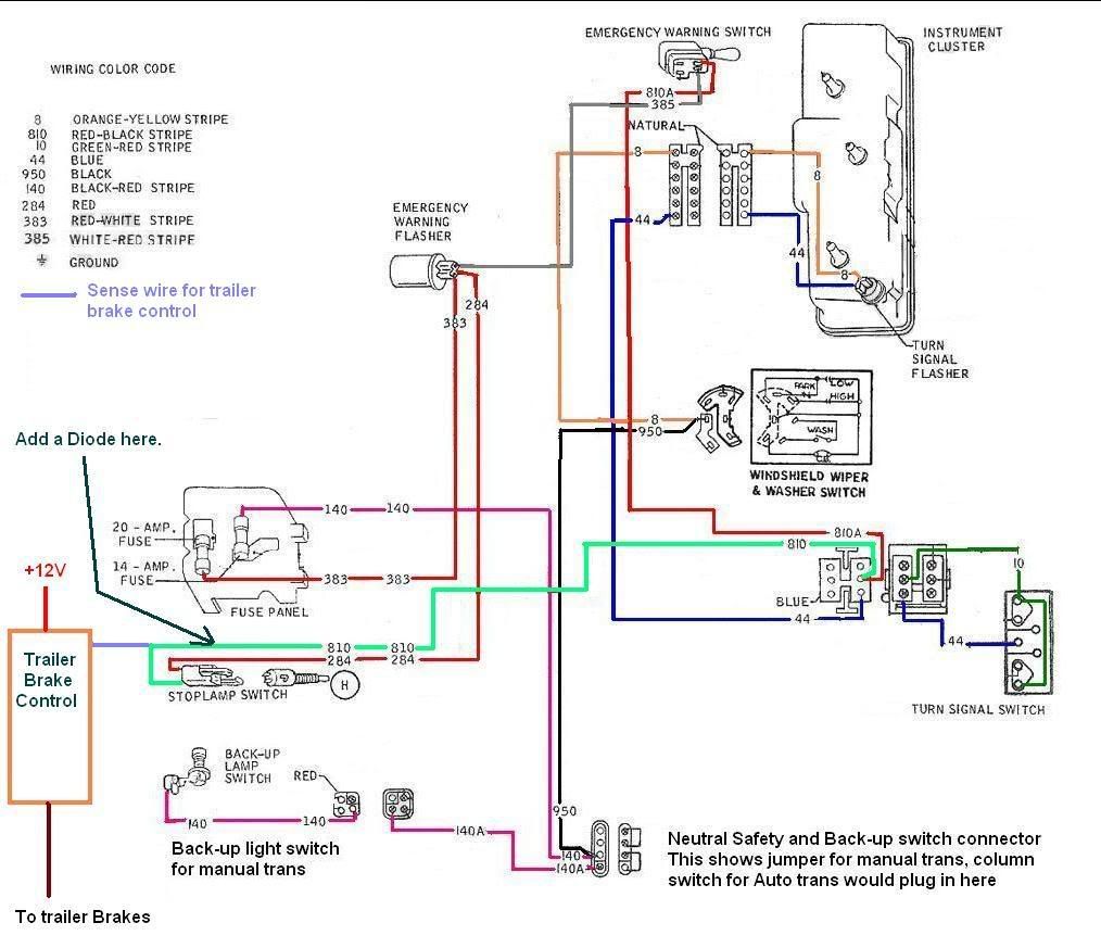
The Emergency lights and the brake lights are connected to the Turn Signal Switch (TSS) at the same point. See the attached diagram at wires 810 and 810A where they go into the TSS. So anytime you use the Emergency lights it will activate the trailer brakes...
To fix this you would need to add a Diode in the brake wire between the TSS and the Brake controller, as Mike58sacco said above. I have noted this in the diagram as well...
Click to expand
As for the problem with the lights flashing with the trailer lights on... The wiring on these old trucks is just barely enough for the truck without adding any other lights to it. You could try a new light switch as the circuit breaker in it could be getting tired, but the best thing to do would be to wire a relay in for the trailer lights.
Here is some information on adding lights that The Fordification site has listed at the bottom of this page http://www.fordification.com/wiring.htm
Adding Lights or Electrical Devices to Ford Light-Duty Trucks
The following information is reproduced directly from the 1970 Ford Body Builder's Layout book (Vol. 70 HTM2-L2). The information is applicable to all '67-'72 trucks.
1) The headlamp switches on all 1970 Ford trucks (except "W" models) employ two integral circuit breakers, one 12-amp for the headlight circuit and one 15-amp for auxiliary circuits. Connections to any point in the circuits controlled by the headlamp switch will be on the auxiliary circuit breaker, except connections to the #12 circuit (headlamp hi-beam, green wire/black stripe), the #13 circuit (headlamp low-beam, red wire/black stripe) and the #15 circuit (feed wire to the dimmer switch, red wire/yellow stripe. Connections to the 12-13 or 15 circuits (headlamp bulb circuits) should be avoided.
If the total load on either headlamp circuit breaker exceeds the breaker rating, the headlamps or tail lamps will cycle on and off indicating the overload. If this occurs, a portion of the added lights must be wired through a relay, feeding the relay coil from the headlamp switch.
The feed from added lights to be controlled by the headlamp switch should be terminated in a male bullet connector and be connected to the female bullet take-out (brown wire -- 285 circuit) on the left-hand side of the instrument panel harness (near the emergency brake). If the vehicle has roof marker lights, this bullet will be occupied by the feed from the roof wires. In this case fabricate a "Y" jumper to permit both connections to the single connector.
Rear lights to be controlled by the headlight switch can be spliced into the #285 circuit (brown wire) at any point in the tail lamp harness.
NOTE: The special Camper option on light trucks provides a plug connector on the left-hand frame rail to which tail lamp connections can be made directly.
Lights controlled by Stop Lamp Switch and Turn Signal Indicator
F100 thru F350 trucks are equipped with a mechanical plunger stop lamp switch which is mounted on the brake pedal arm. This switch is designed for maximum loads usually less than the fuses or circuit breaker in the circuit, but ample for normal stop lamp loads. The maximum load is 12.5 amps and under no circumstances are loads in excess of this value permissible.
If only stop lamp function is desired for the added lights, splice into the 810 circuit (red wire/black stripe) between the stop lamp switch and the turn indicator switch.
If only turn signal function is desired for the added lights, connect right-hand lights to circuit #2 (white wire/blue stripe) and left-hand lights to circuit #3 (green wire/white stripe). This connection can be made by splicing into the wires near the parking lights or near the steering column. (See note below.)
If both turn signal and stop lamp function are desired for the added lights, splice into the taillamp loom, using circuit 282 (green wire) for right-hand lights and circuit 283 (yellow wire/black stripe) for left-hand lights. (See note below.)
NOTE
1) The turn signal switch used on light trucks has a maximum rated current of 6.5 amps for right and left turning functions and 8.0 amps for stop lamp function. Do not exceed these values on the turn signals.
2) The turn signal and emergency flasher system on light trucks utilizes two flashers, one for turn signal and one for emergency flasher function. These flashers are designed to accommodate a two-light (4.2 amps) load for the turn signal flasher and a six-light load (12.6 amps) for the emergency flasher. If one additional 2.1 amp light is added to each side (total 6 lamps) the C8AB-13350-A turn signal flasher must be replaced with a C6AB-13350-B flasher. The addition of two 2.1 amp lamps to each side (total 8 lamps) will require replacing the existing two flasher with a single C8TB-13350-A transistorized flasher and, because of the complexity, is not recommended. The addition of lights without a flasher revision will result in a very fast, unacceptable flashing rate.
Added Lights or Accessories Controlled by Added Switches
For added electrical accessories that operate only when the ignition is on -- terminate the feed wire from the hang-on switch in a bullet connector and plug into the three-way accessory plug on the instrument panel harness (single black wire/green stripe). This circuit is limited by a 14-amp fuse. Fuse "blow" requires the addition of a relay, with the coil fed by a connection to the accessory terminal.
If the added accessory is desired to be operated with the key off, the switch feed can be connected to the cigar lighter (using a "Y" jumper) if the 15-amp fuse for that circuit is sufficient. If heavier loads than the cigar lighter circuit will carry are required, the switch feed should connect to the starter relay "battery" terminal.
Hope this helps you some.

Mike58sacco is correct, this is somewhat normal...
The electronic Trailer Brake Controllers (TBC) have a wire that is hooked to the brake lights. This tells the TBC to activate the trailer brakes and then there is an inertia sensor in the TBC that tells how hard to apply the brakes (along with adjustments).
The Emergency lights and the brake lights are connected to the Turn Signal Switch (TSS) at the same point. See the attached diagram at wires 810 and 810A where they go into the TSS. So anytime you use the Emergency lights it will activate the trailer brakes...
To fix this you would need to add a Diode in the brake wire between the TSS and the Brake controller, as Mike58sacco said above. I have noted this in the diagram as well...
Click to expand
As for the problem with the lights flashing with the trailer lights on... The wiring on these old trucks is just barely enough for the truck without adding any other lights to it. You could try a new light switch as the circuit breaker in it could be getting tired, but the best thing to do would be to wire a relay in for the trailer lights.
Here is some information on adding lights that The Fordification site has listed at the bottom of this page http://www.fordification.com/wiring.htm
Adding Lights or Electrical Devices to Ford Light-Duty Trucks
The following information is reproduced directly from the 1970 Ford Body Builder's Layout book (Vol. 70 HTM2-L2). The information is applicable to all '67-'72 trucks.
1) The headlamp switches on all 1970 Ford trucks (except "W" models) employ two integral circuit breakers, one 12-amp for the headlight circuit and one 15-amp for auxiliary circuits. Connections to any point in the circuits controlled by the headlamp switch will be on the auxiliary circuit breaker, except connections to the #12 circuit (headlamp hi-beam, green wire/black stripe), the #13 circuit (headlamp low-beam, red wire/black stripe) and the #15 circuit (feed wire to the dimmer switch, red wire/yellow stripe. Connections to the 12-13 or 15 circuits (headlamp bulb circuits) should be avoided.
If the total load on either headlamp circuit breaker exceeds the breaker rating, the headlamps or tail lamps will cycle on and off indicating the overload. If this occurs, a portion of the added lights must be wired through a relay, feeding the relay coil from the headlamp switch.
The feed from added lights to be controlled by the headlamp switch should be terminated in a male bullet connector and be connected to the female bullet take-out (brown wire -- 285 circuit) on the left-hand side of the instrument panel harness (near the emergency brake). If the vehicle has roof marker lights, this bullet will be occupied by the feed from the roof wires. In this case fabricate a "Y" jumper to permit both connections to the single connector.
Rear lights to be controlled by the headlight switch can be spliced into the #285 circuit (brown wire) at any point in the tail lamp harness.
NOTE: The special Camper option on light trucks provides a plug connector on the left-hand frame rail to which tail lamp connections can be made directly.
Lights controlled by Stop Lamp Switch and Turn Signal Indicator
F100 thru F350 trucks are equipped with a mechanical plunger stop lamp switch which is mounted on the brake pedal arm. This switch is designed for maximum loads usually less than the fuses or circuit breaker in the circuit, but ample for normal stop lamp loads. The maximum load is 12.5 amps and under no circumstances are loads in excess of this value permissible.
If only stop lamp function is desired for the added lights, splice into the 810 circuit (red wire/black stripe) between the stop lamp switch and the turn indicator switch.
If only turn signal function is desired for the added lights, connect right-hand lights to circuit #2 (white wire/blue stripe) and left-hand lights to circuit #3 (green wire/white stripe). This connection can be made by splicing into the wires near the parking lights or near the steering column. (See note below.)
If both turn signal and stop lamp function are desired for the added lights, splice into the taillamp loom, using circuit 282 (green wire) for right-hand lights and circuit 283 (yellow wire/black stripe) for left-hand lights. (See note below.)
NOTE
1) The turn signal switch used on light trucks has a maximum rated current of 6.5 amps for right and left turning functions and 8.0 amps for stop lamp function. Do not exceed these values on the turn signals.
2) The turn signal and emergency flasher system on light trucks utilizes two flashers, one for turn signal and one for emergency flasher function. These flashers are designed to accommodate a two-light (4.2 amps) load for the turn signal flasher and a six-light load (12.6 amps) for the emergency flasher. If one additional 2.1 amp light is added to each side (total 6 lamps) the C8AB-13350-A turn signal flasher must be replaced with a C6AB-13350-B flasher. The addition of two 2.1 amp lamps to each side (total 8 lamps) will require replacing the existing two flasher with a single C8TB-13350-A transistorized flasher and, because of the complexity, is not recommended. The addition of lights without a flasher revision will result in a very fast, unacceptable flashing rate.
Added Lights or Accessories Controlled by Added Switches
For added electrical accessories that operate only when the ignition is on -- terminate the feed wire from the hang-on switch in a bullet connector and plug into the three-way accessory plug on the instrument panel harness (single black wire/green stripe). This circuit is limited by a 14-amp fuse. Fuse "blow" requires the addition of a relay, with the coil fed by a connection to the accessory terminal.
If the added accessory is desired to be operated with the key off, the switch feed can be connected to the cigar lighter (using a "Y" jumper) if the 15-amp fuse for that circuit is sufficient. If heavier loads than the cigar lighter circuit will carry are required, the switch feed should connect to the starter relay "battery" terminal.
Hope this helps you some.
Shayne
I'm not "Brand Loyal" Ford-Chevy-Dodge-Toyota I have them all, one even cross mixed...
If it Looks good and Works good then it's ok by me. Everything has its issues from time to time...
69 SWB (project) & 69 Highboy (driver/project)
http://s197.photobucket.com/albums/aa29 ... d%20truck/
http://www.fordification.com/galleries/ ... ?cat=10399
-
DGrant09
- New Member
- Posts: 177
- Joined: Wed Jul 11, 2007 10:20 pm
- Location: Palmer, AK
re: 7 Pin Trailer Wiring Issue
That is some good information!! Thank you!!
I have a couple of questions about the diode.
1. What size?
2. Which way should I install it - positive side towards TBC or towards TSS?
I bet I could get one at our auto electric store..
As for the lights - I have yet to try them since I found the two bare wires. Once we get the signal issue fixed I'll try the recommended fix there..
I have to take it one step at a time, keeping it simple!!
Thanks again!!
09", F350, Cabelas, 6.4L
72", F250, CS, 390, 2 WD
72", F250, CS, 390, 2 WD
-
Thunderfoot
- 100% FORDified!
- Posts: 2207
- Joined: Tue Apr 17, 2007 2:34 pm
- Location: Idaho, Boise
re: 7 Pin Trailer Wiring Issue
Radio Shack has Diodes, I would just get a 1 amp or so one (1N4003 should work), as there is almost no current draw for the TBC... Some trailer stores have some Diodes for use in wiring up cars to tow behind motor homes and such, I haven't seen what they look like. The Radio shack ones are cheep, like 2 for a buck 
Just install it with the line around the end (see pic) towards the TSS and get some shrink wrap to cover it all up when done. If you get it backwards you'll know as your brake lights wont work 

Just install it with the line around the end (see pic) towards the TSS and get some shrink wrap to cover it all up when done.
Shayne
I'm not "Brand Loyal" Ford-Chevy-Dodge-Toyota I have them all, one even cross mixed...
If it Looks good and Works good then it's ok by me. Everything has its issues from time to time...
69 SWB (project) & 69 Highboy (driver/project)
http://s197.photobucket.com/albums/aa29 ... d%20truck/
http://www.fordification.com/galleries/ ... ?cat=10399
I'm not "Brand Loyal" Ford-Chevy-Dodge-Toyota I have them all, one even cross mixed...
If it Looks good and Works good then it's ok by me. Everything has its issues from time to time...
69 SWB (project) & 69 Highboy (driver/project)
http://s197.photobucket.com/albums/aa29 ... d%20truck/
http://www.fordification.com/galleries/ ... ?cat=10399
-
DGrant09
- New Member
- Posts: 177
- Joined: Wed Jul 11, 2007 10:20 pm
- Location: Palmer, AK
re: 7 Pin Trailer Wiring Issue
The brake controller issue is fixed!! I'll look into the lights and what you sent here this evening..
Thanks Again!!!
09", F350, Cabelas, 6.4L
72", F250, CS, 390, 2 WD
72", F250, CS, 390, 2 WD
-
DGrant09
- New Member
- Posts: 177
- Joined: Wed Jul 11, 2007 10:20 pm
- Location: Palmer, AK
re: 7 Pin Trailer Wiring Issue
After reading your info Thunderfoot I think the only circuit I need to support would be the tail/running lights. I am considering the following:
1. Read the FRONT of Home Pages from now on!!

2. Figure out exactly how the trailer shop wired this 7 pin last year and make sure there are no other circuits tapping the running light/headlight circuits.
3. Use a relay powered off of the running lights (at the switch) as a control circuit for the tail/running lights rather than having them tapped off of the bed wires. Run the power line from the battery or the fuse box through a 20 amp(?) auto-resetting relay then to the added light relay(?) and finally to the 7 pin.
Pretty much as you suggested.
I have not had any other issues with the other circuits and should be able to leave those alone( Brake/Signals ETC..)
What size circuit breaker and relay would you suggest?
1. Read the FRONT of Home Pages from now on!!
2. Figure out exactly how the trailer shop wired this 7 pin last year and make sure there are no other circuits tapping the running light/headlight circuits.
3. Use a relay powered off of the running lights (at the switch) as a control circuit for the tail/running lights rather than having them tapped off of the bed wires. Run the power line from the battery or the fuse box through a 20 amp(?) auto-resetting relay then to the added light relay(?) and finally to the 7 pin.
Pretty much as you suggested.
I have not had any other issues with the other circuits and should be able to leave those alone( Brake/Signals ETC..)
What size circuit breaker and relay would you suggest?
09", F350, Cabelas, 6.4L
72", F250, CS, 390, 2 WD
72", F250, CS, 390, 2 WD
-
Thunderfoot
- 100% FORDified!
- Posts: 2207
- Joined: Tue Apr 17, 2007 2:34 pm
- Location: Idaho, Boise
re: 7 Pin Trailer Wiring Issue
Yep, that would be the best fix for the trailer tail/running lights...
Sizing kind of depends on how many and type of lights you have on your trailer...
I would go with either a 15 or 20 amp circuit breaker. I would use the bosch style 30A relay as they are easy to get replacements at parts stores and even department stores like Walmart have them... You should be able to get them with the pigtail connector on it to wire it in.
I would run 14 gauge wire at a minimum (12 would be better) back to the back of the truck for this. (again number and types of lights you have will affect this, even the length of the wire run for the truck and trailer will too)
One of my trucks I had before, I ran an 8 gauge 12V power wire back for the 12V power wire for the trailer/trailer battery. Then for the tail/running lights I mounted the relay at the back of the truck and tapped off this power wire for the relay power using a circuit breaker there, and then just used the tail light wire for the activation wire for the relay. Saved running some extra wiring.
Shayne
I'm not "Brand Loyal" Ford-Chevy-Dodge-Toyota I have them all, one even cross mixed...
If it Looks good and Works good then it's ok by me. Everything has its issues from time to time...
69 SWB (project) & 69 Highboy (driver/project)
http://s197.photobucket.com/albums/aa29 ... d%20truck/
http://www.fordification.com/galleries/ ... ?cat=10399
I'm not "Brand Loyal" Ford-Chevy-Dodge-Toyota I have them all, one even cross mixed...
If it Looks good and Works good then it's ok by me. Everything has its issues from time to time...
69 SWB (project) & 69 Highboy (driver/project)
http://s197.photobucket.com/albums/aa29 ... d%20truck/
http://www.fordification.com/galleries/ ... ?cat=10399
-
kaptnkaos

- 100% FORDified!
- Posts: 2029
- Joined: Thu Feb 16, 2006 1:27 am
- Location: Washington, Elma
re: 7 Pin Trailer Wiring Issue
Hey Thunderfoot...
Good ta see ya out and about...
I have a question along these lines as well.
On my CS (since it has a separate camper harness), do I need to do anything like install relays to run the lights on the camper???
I did have to tap into the brown wire going back to the tail-lights because the tail-light wire on the stock camper harness was dead.
What about the hooking up the bump trailer?
I haven't gotten the 7 blade / 4way flat connecter installed and wired on the truck yet.
Will I need to install relays or anything for it?
I am planning on coming off of the camper harness with it as well.
KaptnKA S
S
Good ta see ya out and about...
I have a question along these lines as well.
On my CS (since it has a separate camper harness), do I need to do anything like install relays to run the lights on the camper???
I did have to tap into the brown wire going back to the tail-lights because the tail-light wire on the stock camper harness was dead.
What about the hooking up the bump trailer?
I haven't gotten the 7 blade / 4way flat connecter installed and wired on the truck yet.
Will I need to install relays or anything for it?
I am planning on coming off of the camper harness with it as well.
KaptnKA
Washington...The land where rust is like the family pet...Ya learn to live with it and clean up after its mess... KaptnKAOS
"Olde Skool" '68 Ford Bluebird short bus
"FRODO" '68 F-250 Camper Special project
"Olde Skool" '68 Ford Bluebird short bus
"FRODO" '68 F-250 Camper Special project
-
FLATBEDFORD

- 100% FORDified!
- Posts: 1818
- Joined: Sat Feb 18, 2006 1:34 pm
- Location: New York, Crugers
- Contact:
Re: re: 7 Pin Trailer Wiring Issue
This is what I was thinking of doing. That way the trailer lights would be isolated from the truck's lights with their own fuses/circuit breakers as they are on the newer trucks. That would solve the problem of the weak electrics on these old trucks, especially if you're dealing with a larger trailer with lots of lights. I read about a setup for this years ago in a magazine, but haven't been able to find it. It used the tow vehicle's wiring only for switching, but powered the lights with a separate power supply. i suppose it could also power the brake controller.Thunderfoot wrote:Y
One of my trucks I had before, I ran an 8 gauge 12V power wire back for the 12V power wire for the trailer/trailer battery. Then for the tail/running lights I mounted the relay at the back of the truck and tapped off this power wire for the relay power using a circuit breaker there, and then just used the tail light wire for the activation wire for the relay. Saved running some extra wiring.
Steve
1970 F350 DRW Factory 9' Platform/Stake, 360, T18.
Passed on to new care taker July, 2013
My Photo Gallery
http://s115.photobucket.com/albums/n298/flatbedford/
1970 F350 DRW Factory 9' Platform/Stake, 360, T18.
Passed on to new care taker July, 2013
My Photo Gallery
http://s115.photobucket.com/albums/n298/flatbedford/
-
DGrant09
- New Member
- Posts: 177
- Joined: Wed Jul 11, 2007 10:20 pm
- Location: Palmer, AK
re: 7 Pin Trailer Wiring Issue
Today was spent figuring out this relay but I do believe we have the issue resolved! I did not pull the trailer anywhere but the lights stayed on for a 15 minute record.

I ran the setup as mentioned above. I just took me 3 or 4 tries on getting this relay wired correctly!
One last question, the emergency flashers seem to be pretty week now. Is a higher rated flasher available that may better support these?
Thanks a million!!
Dan
I ran the setup as mentioned above. I just took me 3 or 4 tries on getting this relay wired correctly!
One last question, the emergency flashers seem to be pretty week now. Is a higher rated flasher available that may better support these?
Thanks a million!!
Dan
09", F350, Cabelas, 6.4L
72", F250, CS, 390, 2 WD
72", F250, CS, 390, 2 WD
-
Thunderfoot
- 100% FORDified!
- Posts: 2207
- Joined: Tue Apr 17, 2007 2:34 pm
- Location: Idaho, Boise
Re: re: 7 Pin Trailer Wiring Issue
Dan,DGrant09 wrote:Today was spent figuring out this relay but I do believe we have the issue resolved! I did not pull the trailer anywhere but the lights stayed on for a 15 minute record.
I ran the setup as mentioned above. I just took me 3 or 4 tries on getting this relay wired correctly!
One last question, the emergency flashers seem to be pretty week now. Is a higher rated flasher available that may better support these?
Thanks a million!!
Dan
Glad you got it all hooked up and it's working good!
On the Emergency Flasher... Yes, you can get a "Heavy Duty" Flasher for it, that may help it some. When you go to the parts store for it, just ask for a "Heavy Duty" one.
Shayne
I'm not "Brand Loyal" Ford-Chevy-Dodge-Toyota I have them all, one even cross mixed...
If it Looks good and Works good then it's ok by me. Everything has its issues from time to time...
69 SWB (project) & 69 Highboy (driver/project)
http://s197.photobucket.com/albums/aa29 ... d%20truck/
http://www.fordification.com/galleries/ ... ?cat=10399
I'm not "Brand Loyal" Ford-Chevy-Dodge-Toyota I have them all, one even cross mixed...
If it Looks good and Works good then it's ok by me. Everything has its issues from time to time...
69 SWB (project) & 69 Highboy (driver/project)
http://s197.photobucket.com/albums/aa29 ... d%20truck/
http://www.fordification.com/galleries/ ... ?cat=10399
-
Thunderfoot
- 100% FORDified!
- Posts: 2207
- Joined: Tue Apr 17, 2007 2:34 pm
- Location: Idaho, Boise
Re: re: 7 Pin Trailer Wiring Issue
kaptnkaos wrote:Hey Thunderfoot...
Good ta see ya out and about...
I have a question along these lines as well.
On my CS (since it has a separate camper harness), do I need to do anything like install relays to run the lights on the camper???
I did have to tap into the brown wire going back to the tail-lights because the tail-light wire on the stock camper harness was dead.
What about the hooking up the bump trailer?
I haven't gotten the 7 blade / 4way flat connecter installed and wired on the truck yet.
Will I need to install relays or anything for it?
I am planning on coming off of the camper harness with it as well.
KaptnKA
Sorry for the delay...I was out Friday and most the weekend.
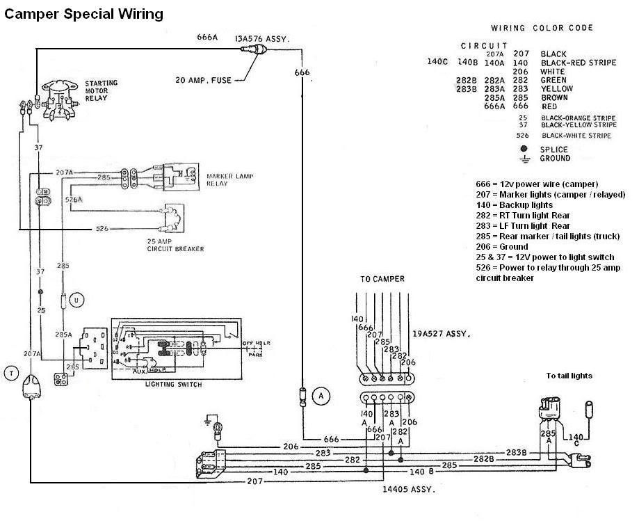
For your camper, it is already hooked up to a relay for the marker lights on it, see diagram below I made up to better show the Camper Special Wiring.
207 is the relayed power for the marker lights on the camper. For your trailer, if you tap into this 207 wire for the tail / marker lights then it would be great!
If you were not getting any power on this line for the camper, then check the circuit breaker and be sure it has power to and out of it, then check the relay for power from the light switch and power out of the relay. After that it, it is the wire or connection somewhere.
Let me know how it goes and if you find anything that differs from my diagram so I can update it.
Shayne
I'm not "Brand Loyal" Ford-Chevy-Dodge-Toyota I have them all, one even cross mixed...
If it Looks good and Works good then it's ok by me. Everything has its issues from time to time...
69 SWB (project) & 69 Highboy (driver/project)
http://s197.photobucket.com/albums/aa29 ... d%20truck/
http://www.fordification.com/galleries/ ... ?cat=10399
I'm not "Brand Loyal" Ford-Chevy-Dodge-Toyota I have them all, one even cross mixed...
If it Looks good and Works good then it's ok by me. Everything has its issues from time to time...
69 SWB (project) & 69 Highboy (driver/project)
http://s197.photobucket.com/albums/aa29 ... d%20truck/
http://www.fordification.com/galleries/ ... ?cat=10399
-
FLATBEDFORD
- 100% FORDified!
- Posts: 1818
- Joined: Sat Feb 18, 2006 1:34 pm
- Location: New York, Crugers
- Contact:
I think my F350 platform/stake has something similar for the marker lights on the bed.
Steve
1970 F350 DRW Factory 9' Platform/Stake, 360, T18.
Passed on to new care taker July, 2013
My Photo Gallery
http://s115.photobucket.com/albums/n298/flatbedford/
1970 F350 DRW Factory 9' Platform/Stake, 360, T18.
Passed on to new care taker July, 2013
My Photo Gallery
http://s115.photobucket.com/albums/n298/flatbedford/