1967 Wiring at starter solenoid
Moderators: FORDification, Thunderfoot
-
kaliona
- New Member

- Posts: 81
- Joined: Fri Feb 24, 2012 7:51 pm
- Location: Northern California
1967 Wiring at starter solenoid
I'm trying to figure out what the p.o. did with the wiring at the starter solenoid. He hooked up an aftermarket ammeter for some reason and I want to disconnect it and use the original dash mounted ammeter. Can someone with a '67 post a pic of your wiring at the starter solenoid? Please!!! This is what mine looks like, with the p.o.'s ammeter tapped in (big red wires), and it doesn't look anything like the wiring diagram I got from the technical section of this site. Thanks guys.
You do not have the required permissions to view the files attached to this post.
- bluef250
- Blue Oval Fanatic

- Posts: 924
- Joined: Fri Oct 29, 2004 8:49 pm
- Location: Arizona
Re: 1967 Wiring at starter solenoid
Where is the larger black wire attached?
What type of ammeter?
What type of ammeter?
-
kaliona
- New Member

- Posts: 81
- Joined: Fri Feb 24, 2012 7:51 pm
- Location: Northern California
Re: 1967 Wiring at starter solenoid
Looks like large black wire goes to alternator. Don't know what kind of ammeter, so here's a pic. It has the two red wires from its terminals that are seen in my first pic and a terminal for the light bulb.
You do not have the required permissions to view the files attached to this post.
-
mrollings53
- Blue Oval Fan

- Posts: 617
- Joined: Mon May 10, 2010 6:09 pm
- Location: Tacoma, WA
Re: 1967 Wiring at starter solenoid
I would definitely lose that ammeter. All of the power in your truck runs through those two little wires. Disconnect those two wires and connect the black wire to the battery terminal on the solenoid.
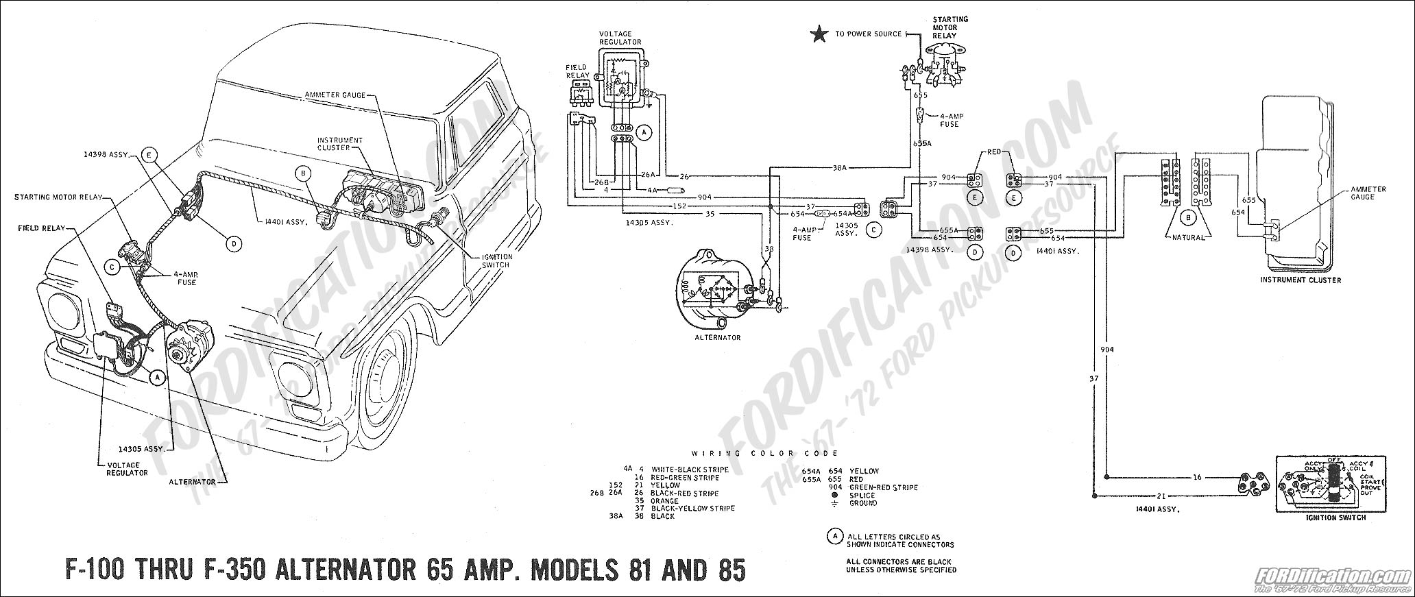
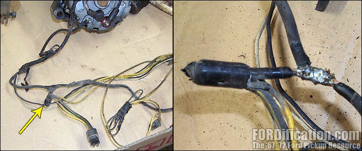
From the back of the stock gauge trace the red and yellow wires. The red wire should connect to the battery terminal on the solenoid with a 4 amp inline fuse. The yellow wire should splice into the same spot as the charge wire from the alternator and the main power wire for the cab with another 4 amp fuse. Follow that black wire in your picture towards the alternator. Before you get there you should see a nasty looking jumble of wires coming together. Here you'll have a black/yellow stripe wire spliced to the charge wire from the alternator, and another wire heading toward the voltage regulator. This splice is where the yellow wire is supposed to connect.
The stock ammeter is wired this way so that you don't need to run something like a 8 gauge wire to and from the gauge. This reduces the risk of fire, because all of the power from the battery or alternator must first run through the gauge; like in your current setup.
Here's a diagram that should get you setup correctly. Follow wires 654(yellow) and 655(red).

Here's a pic of what the shunt should look like too.

From the back of the stock gauge trace the red and yellow wires. The red wire should connect to the battery terminal on the solenoid with a 4 amp inline fuse. The yellow wire should splice into the same spot as the charge wire from the alternator and the main power wire for the cab with another 4 amp fuse. Follow that black wire in your picture towards the alternator. Before you get there you should see a nasty looking jumble of wires coming together. Here you'll have a black/yellow stripe wire spliced to the charge wire from the alternator, and another wire heading toward the voltage regulator. This splice is where the yellow wire is supposed to connect.
The stock ammeter is wired this way so that you don't need to run something like a 8 gauge wire to and from the gauge. This reduces the risk of fire, because all of the power from the battery or alternator must first run through the gauge; like in your current setup.
Here's a diagram that should get you setup correctly. Follow wires 654(yellow) and 655(red).

Here's a pic of what the shunt should look like too.

Common Sense is an Uncommon Virtue
-
kaliona
- New Member

- Posts: 81
- Joined: Fri Feb 24, 2012 7:51 pm
- Location: Northern California
Re: 1967 Wiring at starter solenoid
Thanks for the info mrollings, but your diagram is for a '69. Would that apply to my '67? I don't see any of the in-line fuses you mentioned. I do have the red and yellow wires, but they are crimped together to the same connector and it looks like factory wiring. I included a close up of this connector along with a pic showing the wire harness coming through the firewall and another pic showing where the big black wire goes down the inner fender connecting to another mess of wires where I can see that black/yellow wire you mentioned. Can I just remove those two red wires and connect the yellow, red, and black wires to the battery terminal on the solenoid?
You do not have the required permissions to view the files attached to this post.
-
mrollings53
- Blue Oval Fan

- Posts: 617
- Joined: Mon May 10, 2010 6:09 pm
- Location: Tacoma, WA
Re: 1967 Wiring at starter solenoid
That's not the correct way to wire them if those are the ammeter gauge wires. Test continuity between the red and yellow wires at the solenoid and the wires at the back of the gauge. If they are connected, you'll need to cut off that ring terminal, add 4 amp fuses to each wire and connect them like I said in my earlier post. If they are not connected, I suggest cutting the tape off the wires and following them to their destination. As is, they can stay connected to the battery terminal on the starter solenoid. It hasn't caused any issues yet has it? Once you know what they do you can determine where they actually belong.
Lose the aftermarket ammeter wiring, and hook that black wire from the alternator to the battery terminal on the starter solenoid. One bump, and that wire is shorting out on your fender or battery.
Lose the aftermarket ammeter wiring, and hook that black wire from the alternator to the battery terminal on the starter solenoid. One bump, and that wire is shorting out on your fender or battery.
Common Sense is an Uncommon Virtue
-
kaliona
- New Member

- Posts: 81
- Joined: Fri Feb 24, 2012 7:51 pm
- Location: Northern California
Re: 1967 Wiring at starter solenoid
I checked for continuity between the wire at the solenoid and the back of the ammeter. "Red" wire has continuity, "Yellow" wire no continuity. I'm going to remove the two red wires from the aftermarket ammeter and connect the Red, Yellow, and Black wires to the battery terminal of the solenoid and see what happens.
Anyone else out there with a '67 who can take a pic of the wiring at their solenoid. That might put my mind at ease that the previous owner didn't mess with the original wiring (but I still wonder why the aftermarket ammeter in the first place). I'm disappointed with the wiring diagram in the Tech section. It doesn't even show the ammeter in any of the diagrams. And it shows that there should be a BLK/YEL wire to the solenoid, which I don't have.
mrollings: thanks for your suggestions. I don't want to start tearing into the wiring harnesses yet, but I may have to eventually.
-
mrollings53
- Blue Oval Fan

- Posts: 617
- Joined: Mon May 10, 2010 6:09 pm
- Location: Tacoma, WA
Re: 1967 Wiring at starter solenoid
I checked some photos I took from when I installed my 3G alternator. I also have that yellow and red wire ring terminal like yours connected to the solenoid. I think the yellow wire goes to the horn circuit. So hooking it straight up should be okay. Before you hook the black wire up check continuity between it and the yellow wire at the back of the stock ammeter. If the original wiring is still there they should be connected through the shunt, and you should see continuity between the yellow wire and the black wire.
You do not have the required permissions to view the files attached to this post.
Common Sense is an Uncommon Virtue