wiring problems
Moderators: FORDification, Thunderfoot
-
smilinsam
- New Member

- Posts: 33
- Joined: Tue Oct 30, 2012 11:43 am
wiring problems
Hi y'all!...just got through installing and wiring an F-600 instrument cluster, in which I replaced the stock gauges with SW's. It works fine except for the volt-meter (I replaced the stock ammeter). It wants to bounce around, registering anywhere from 13 to 16 volts...it sometimes stays at 14.5 but it "twitches" when the turn signals are on. The truck has had this problem since I bought it. I've replaced the alternator, regulator and solenoid...and a good part of the original wiring and connectors. I also bypassed the constant voltage regulator on the instrument cluster and powered the gauges with an ignition wire...my thinking was I have wired many gauges without a regulator and, since the gauges were all new, I shouldn't have to wire up the old regulator...which I thought was my problem. Well...that didn't work. A couple of mechanics around here say it is a "ground problem," but I have cleaned, rerouted and replaced every ground I can find, without any luck. Does anyone have any ideas?...and is it necessary to run that constant voltage regulator? Thanks for any help!
- bluef250
- Blue Oval Fanatic

- Posts: 924
- Joined: Fri Oct 29, 2004 8:49 pm
- Location: Arizona
Re: wiring problems
Do the SW gauges use 12 volt source?
Tapping the voltage closer to source might eliminate some of the bounce. The tack uses the distributor + side, I believe, which might be a good place as it is hot when the engine is running or starting.
Tapping the voltage closer to source might eliminate some of the bounce. The tack uses the distributor + side, I believe, which might be a good place as it is hot when the engine is running or starting.
- Calfdemon
- 100% FORDified!

- Posts: 2672
- Joined: Tue May 25, 2010 11:31 pm
- Location: California, Santa Clarita
Re: wiring problems
If you are running aftermarket gauges, then you do not need to use the stock IPVR and can bypass it, as you have.. I do not have an answer as to why your gauge is bouncing like that, but the IPVR is not the reason. I would have thought maybe you needed a new voltage regulator as maybe you were actually spiking at times and your gauge was reading properly, but you stated you already changed the regulator, as well as the alternator. This is a tough one to pinpoint without being there and having hands on. Have you used a voltmeter to see if you are actually getting fluctuating voltage through the system?
If the gauge is reading through the ignition system, then that would be the first place I would start with the voltmeter. If your voltage is fluctuating with the blinkers, then you probably have it on the same power circuit that feeds your blinker lights and possibly other items. When those items are used, the power to your volt meter might be cut significantly from the draw if the wiring is not enough to handle all of the draws. This might be your problem.
I ran an 8 gauge wire directly from my starter solenoid to a group of relays that I installed under my dash. I then power the relays "on" with a wire from my ignition. I used one of these relays which is directly route to my charging system for my instrument gauges including my volt meter and I get no fluctuations with items being turned on. But again, it is run off a different circuit which is routed directly from where the alternator hooks to the starter solenoid.
-Rich
Current toys -
69 Ford F350 Crew Cab - 460 / C6 - http://i253.photobucket.com/albums/hh67 ... lqgskp.jpg
31 Ford Vicky - 1955 270 Red Ram Hemi / 4 speed - http://i253.photobucket.com/albums/hh67 ... bsibvn.jpg
Former toys -
67 Pontiac Firebird 400 convertible (sold 9/13) - http://i253.photobucket.com/albums/hh67 ... bird-1.jpg
67 Ford Fairlane GT - 390 / 4 speed (sold 7/15) - http://i253.photobucket.com/albums/hh67 ... c5hu8z.jpg
-
smilinsam
- New Member

- Posts: 33
- Joined: Tue Oct 30, 2012 11:43 am
Re: wiring problems
Hi Calfdemon! Thanks for the input...I think originally there are two "hot wires" coming from the multiwire connector...one black with a white stripe and one black with a green stripe...there's an additional live wire which is yellow that goes to the ammeter. I disconnected all three and fed the whole panel with one wire coming from the ignition. I can see from what you're saying that the turn signals could feed that intermitten pulse into the circuit and that would account for the "twitch." What's driving me crazy is the fluctuation in voltage, but maybe I can split it up and isolate it by creating another circuit using relays as you did. Do you remember where you got those relays and what are the specs? I saw your picture of the installation and it looked real neat. By the way, you inspired the f-600 swap and it looks awesome! (as the kids say...but we're all just kids....just older!)
- Calfdemon
- 100% FORDified!

- Posts: 2672
- Joined: Tue May 25, 2010 11:31 pm
- Location: California, Santa Clarita
Re: wiring problems
Thanks for the props on my F600 thread. Its nice to know that people actually look at it from time to time and that it inspires or helps. I got my inspiration to do it the same way from someone else, but of course, took some of my own turns.
Anyway, if you want to go the relay route, these are the types of relays that I used: http://www.parts-express.com/pe/showdet ... er=330-073
You also will want the sockets for them: http://www.parts-express.com/pe/showdet ... er=330-075
I actually ran 2 dual sockets for my 4 relays which actually made it easier to mount since it connected 2 into 1: http://www.parts-express.com/pe/showdet ... er=330-078
For our purposes, the red wire will be cut and not used. The white wire is wired to your ignition and will turn your relay on and off. The yellow is for constant hot (run a fuse in this line), the black is obviously ground, and the blue is the outgoing power to the item you want to run with your relay.
You can run just one if you want, but it is always better to run more than you need and that way you have new connection spots if you ever want to add anything. I ran 4 of them and ended up using them all. Just make sure that you run a big enough power wire to the relays (yellow) if you are going to run multiples. And again, run a fuse for each relay in between the yellow wire and your constant hot that is appropriate for what you are hooking up to it so you don't fry anything.
-Rich
Current toys -
69 Ford F350 Crew Cab - 460 / C6 - http://i253.photobucket.com/albums/hh67 ... lqgskp.jpg
31 Ford Vicky - 1955 270 Red Ram Hemi / 4 speed - http://i253.photobucket.com/albums/hh67 ... bsibvn.jpg
Former toys -
67 Pontiac Firebird 400 convertible (sold 9/13) - http://i253.photobucket.com/albums/hh67 ... bird-1.jpg
67 Ford Fairlane GT - 390 / 4 speed (sold 7/15) - http://i253.photobucket.com/albums/hh67 ... c5hu8z.jpg
Current toys -
69 Ford F350 Crew Cab - 460 / C6 - http://i253.photobucket.com/albums/hh67 ... lqgskp.jpg
31 Ford Vicky - 1955 270 Red Ram Hemi / 4 speed - http://i253.photobucket.com/albums/hh67 ... bsibvn.jpg
Former toys -
67 Pontiac Firebird 400 convertible (sold 9/13) - http://i253.photobucket.com/albums/hh67 ... bird-1.jpg
67 Ford Fairlane GT - 390 / 4 speed (sold 7/15) - http://i253.photobucket.com/albums/hh67 ... c5hu8z.jpg
-
smilinsam
- New Member

- Posts: 33
- Joined: Tue Oct 30, 2012 11:43 am
Re: wiring problems
Thanks again Calfdemon!...I ordered the relays and connectors you suggested and I'll let you know how it turns out...I've built a lot of cars over the years but just as a hobby...the one area that mystifies me is electrical, but the cost of professional help these days means it's time to learn! 
- Calfdemon
- 100% FORDified!

- Posts: 2672
- Joined: Tue May 25, 2010 11:31 pm
- Location: California, Santa Clarita
Re: wiring problems
Sounds good... And on a side note, I gave you wire colors based on how my sockets were wired. I am not sure if different brands might use different wiring locations. So before you just go off of what I said above, we might want to compare what you get to what I have so we can make sure they are set up the same way. My truck is completely apart right now and all of my wiring is removed, so I have easy access to my relays and sockets. Here are a few pictures so you can make sure the ones you get are set up the same way...
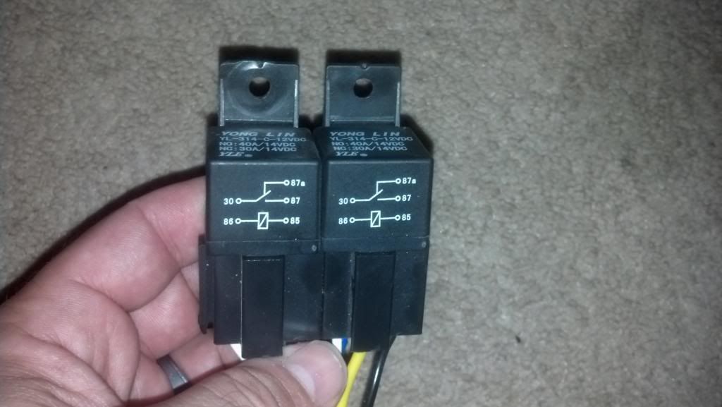
Here are the "front" of the relays and also the relay diagram for comparison to yours:

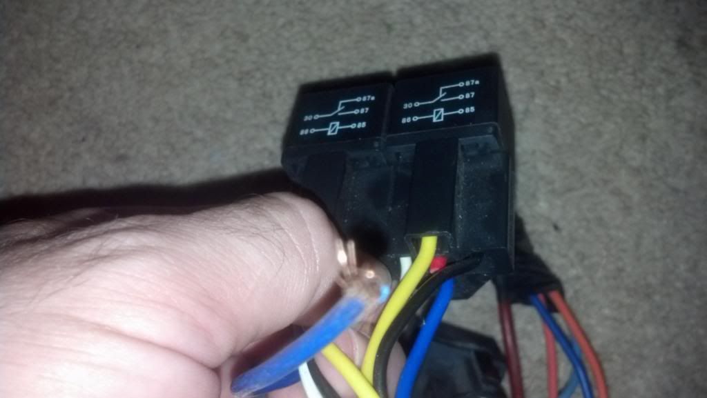
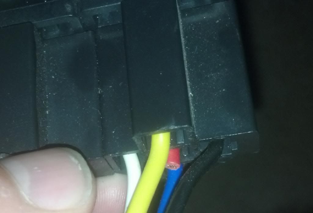
And here is a look at the wiring and color configuration of mine... Yellow to the front, blue to the back, white to the left, black to the right, and red (cut) was center:


I believe they are all set up the same way, but just in case, I wanted to give you something to look at for comparison.
Here are the "front" of the relays and also the relay diagram for comparison to yours:

And here is a look at the wiring and color configuration of mine... Yellow to the front, blue to the back, white to the left, black to the right, and red (cut) was center:


I believe they are all set up the same way, but just in case, I wanted to give you something to look at for comparison.
-Rich
Current toys -
69 Ford F350 Crew Cab - 460 / C6 - http://i253.photobucket.com/albums/hh67 ... lqgskp.jpg
31 Ford Vicky - 1955 270 Red Ram Hemi / 4 speed - http://i253.photobucket.com/albums/hh67 ... bsibvn.jpg
Former toys -
67 Pontiac Firebird 400 convertible (sold 9/13) - http://i253.photobucket.com/albums/hh67 ... bird-1.jpg
67 Ford Fairlane GT - 390 / 4 speed (sold 7/15) - http://i253.photobucket.com/albums/hh67 ... c5hu8z.jpg
Current toys -
69 Ford F350 Crew Cab - 460 / C6 - http://i253.photobucket.com/albums/hh67 ... lqgskp.jpg
31 Ford Vicky - 1955 270 Red Ram Hemi / 4 speed - http://i253.photobucket.com/albums/hh67 ... bsibvn.jpg
Former toys -
67 Pontiac Firebird 400 convertible (sold 9/13) - http://i253.photobucket.com/albums/hh67 ... bird-1.jpg
67 Ford Fairlane GT - 390 / 4 speed (sold 7/15) - http://i253.photobucket.com/albums/hh67 ... c5hu8z.jpg
-
smilinsam
- New Member

- Posts: 33
- Joined: Tue Oct 30, 2012 11:43 am
Re: wiring problems
Thanks once more Calfdemon!...I'll let you know of progress. I've got to get my 14 yr. old son to teach me how to put photos on here!...they sure do help. I've done quite a lot to "big red" (72 camper special f-250 428 c-6)since acquiring her from your neck of the woods...next project is install "old-air" kit but I have to solve wiring gremlins first...looks like those relays willl be the way to go in hooking up the air unit...