Any ideas of where to start before I buy new gauges or a complete new wiring harness?
Any advice is appreciated.
Moderators: FORDification, Thunderfoot
Gotcha....thanks for the tip. I'll have to take a look and check it out.fordman wrote:Instrument Panel Voltage Regulator. figure 5 and 7 on this page. http://www.fordification.com/tech/fuel- ... -units.htm
Fordman, I've tested the gauges and Ipvr with a 9v battery like you advised. The gauges all pegged so I assume the gauges are operational and good. Same with the Ipvr. That seems to work per your method above with hooking the battery to the inside/incoming post of the Ipvr. I used one of those circuit tester pens that light up when it senses a power/hot wire and tested the cluster connector, fuses, fuse panel, and they all seem to work (it lit up). I tested the orange wire to the fuel sending unit with the pen light and it did NOT light up. So.......would it seem logical that the problem is the circuit board? Would that also explain the lack of power going to the orange wire of the fuel sending unit? I don't know what else it could be?fordman wrote:i was using apower supply in the house wire a bare wire coming off of it. i stuck the wire inside of the hole in the ivpr. where my finger is pointing at. while that was hooked up i used the ground side of the power supply to the threads on each gauge. i tested each one individually. one at a time just movign the ground wire from one gauge to the other.
So looks like it is most likely the circuit board since the ipvr seems to be operating....at least that's my guess? I'll probably have to research where to buy a new one, perhaps from LMC or DC or Mac's. Is there any trick to installing a new board or is it pretty simple?fordman wrote:the orange wire isnt a power wire. its just a sensor wire. 1 power wires goes into the plug. you may also find a second wire that i shot for the alt gauge. the rest of the wires are just sensor wires. in and out the power is all in the circuit board and ivpr once power comes in from the plug to the circuit board.

Thanks Fordman. That makes me feel a little better in the event that I do need to switch out the circuit board. I tend to dive in and then totally "screw it up".fordman wrote:installation is easy. i have a used board for a 71 /72 with full gauges.
Thanks Thunderfoot for the advice. I'll do a little more research on this and give it a try. I feel like I'm close to figuring out the problem but close doesn't quite solve the problem!Thunderfoot wrote:I might of missed it in your posts but if you take the sense wires at the sensors (water, oil, and fuel) and unplug them from the sensor and touch the connector to ground the gauge will peg like you did on the instrument panel test, this will tell you if the wire and circuit board are good if they peg out and that the sensor is bad.
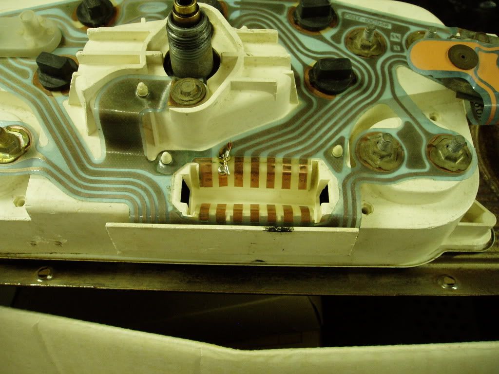
All the Sense wires (Orange-Fuel, White/red striped-oil, and Red/white striped-water) should have a pulsing power on them with the key on... If you don't have this power on these wires check the pad on the circuit board where the connector makes contact for power to see if it has power there, it is a common problem with these circuit boards for the pads to get dirty and make bad contact, you can clean them with a pencil eraser. Also you can usually see if the trace in the circuit board is bad by a visual inspection of it. Here is a picture below of my F600 cluster that had a broken connection that I did a quick (not so pretty) fix on. If you have power on the connector pad then check that the wire is making good connection to the connector pin and that the pin is making good contact with the circuit board pad.
For the Amp gauge; both the red and yellow wires for the Amp gauge should have power on them all the time (key on or off), there are in-line fuses in the wires by the alternator and starter solenoid for these wires.